
AMP Magnetics is an independent manufacturer’s representative for specialized domestic manufacturers of 3-phase line reactors, load reactors, and precision DC power inductors.
Variable frequency drives draw non-sinusoidal current pulses that distort line voltage and stress utility supplies. On the motor side, high-frequency IGBT inverter switching generates rapid voltage rise times (dv/dt) and reflected wave phenomena that degrade motor winding insulation and ruin bearings.
As a manufacturer’s representative, AMP Magnetics provides direct access to plant engineers who build ruggedized air-gapped iron core reactors designed to absorb line disturbances, damp harmonic spikes, and extend motor lifespan.
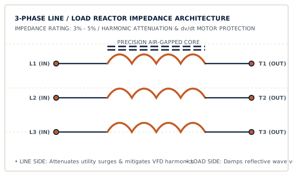
Our represented principals manufacture magnetic choke components across these core configurations:
| Component Class | Typical Impedance | Current Ratings | Operational Function & Placement |
|---|---|---|---|
| Line Reactors (Input) | 3% or 5% Standard | 2A to 1,200A+ (600V Max) | Installed upstream between the power source and the VFD. Suppresses utility line surges, mitigates cross-talk, and reduces VFD input THD-i. |
| Load Reactors (Output) | 3% Standard | 2A to 1,200A+ | Installed between the VFD and AC induction motor. Damps peak voltage spikes on long cable leads (typically > 50 ft), reduces motor acoustic noise, and lowers operating temperatures. |
| dv/dt Output Filters | Specialized LC Network | Up to 1,000A | Slows voltage rise time (< 200V/μs) to protect non-inverter-duty motors and lead lengths up to 1,000 feet from catastrophic insulation punch-through. |
| DC Link Chokes | Application Tailored | 10A to 800A DC | Mounted in the VFD intermediate DC bus. Smooths DC ripple current, improves input power factor to > 0.90, and reduces AC line harmonics. |
| Harmonic Detuned Chokes | 5.67%, 7%, 14% | Sized to capacitor bank | Connected in series with power factor correction capacitors to prevent electrical resonance at 5th, 7th, or 11th harmonic frequencies. |
Recommended for general-purpose drive installations where the power feed is relatively stable and clean. Provides sufficient surge attenuation to prevent nuisance drive tripping while maintaining minimal voltage drop at full load.
Essential for stiff power grids (low source impedance), facilities operating adjacent to large welding or arc loads, or applications requiring strict compliance with preliminary IEEE 519 targets before active filtering.
Provide your drive horsepower, full-load amps, voltage, and lead length for an immediate technical review and factory quote.
Request Reactor Quote